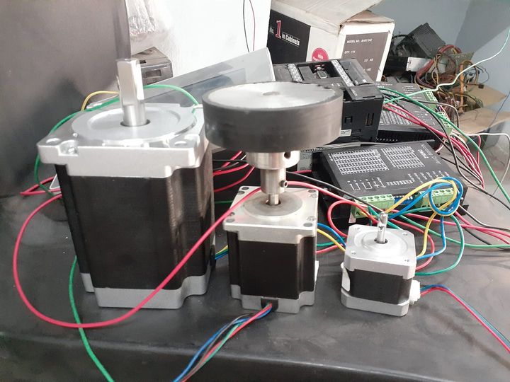
The stepper motor is not run without stepper control or a PWM signal generator. a stepper motor is a permanent magnet motor that’s why it rotates 1.8-degree angle of rotation. stepper motors are 4 or 6 wires. check the continuity between pairs of wire then connect to a motor with continuity wire pair A+, A-coil with the driver side .same as next pair, power on or check if the motor shaft is held then means a connection of motor and driver is right, after this, you can control your motor with driver input pin pulse and direction pin given in the driver housing, same given as image below.


The internal working structure of the stepper motor


Arduino code for stepper motor direction control using PUSH-BUTTON

Arduino code for stepper motor direction  control using proximity sensorOR PUSH BUTTON
#include <Stepper.h>
// defines pins numbers
const int stepPin = 8;
const int dirPin = 9;
const int enPin = 10;
const int LimitSwitch_LEFT_Pin  = 4;
const int LimitSwitch_RIGHT_Pin = 5;


const int stepsPerRevolution =400;  // change this to fit the number of steps per revolution
// for your motor


// initialize the stepper library on pins 8 through 11:
Stepper myStepper(stepsPerRevolution, 5, 5, 2, 2);

int stepCount = 0;  // number of steps the motor has taken

void setup() {
  // nothing to do inside the setup

  pinMode(LimitSwitch_LEFT_Pin , INPUT);
  pinMode(LimitSwitch_RIGHT_Pin , INPUT);

  // Sets the two pins as Outputs
  pinMode(stepPin,OUTPUT);
  pinMode(dirPin,OUTPUT);

  pinMode(enPin,OUTPUT);
  digitalWrite(enPin,LOW);

  // Set Dir to Home switch
  digitalWrite(dirPin,HIGH); // Enables the motor to move in a particular direction


}

void loop() {

 // read the sensor value:
  int sensorReading = analogRead(A0);
  // map it to a range from 0 to 100:
  int motorSpeed = map(sensorReading, 0,1024,0,20);
  // set the motor speed:
  if (motorSpeed > 0) {
    myStepper.setSpeed(motorSpeed);
    // step 1/100 of a revolution:
    myStepper.step(stepsPerRevolution /6400);
  }


 int leftSw  = digitalRead( LimitSwitch_LEFT_Pin);
    int rightSw = digitalRead( LimitSwitch_RIGHT_Pin);

    if( (leftSw  == HIGH && (digitalRead(dirPin) == HIGH)) ||
        (rightSw == HIGH && (digitalRead(dirPin) == LOW)) ){

        motorStep(1);

    }
    else if( leftSw == LOW && (digitalRead(dirPin) == HIGH) ){
          digitalWrite(dirPin,LOW);

    }
    else if( rightSw == LOW && (digitalRead(dirPin) == LOW ) ){
          digitalWrite(dirPin,HIGH);
        ///


    }

}

void motorStep( int MAX){

   for(int x = 0; x < MAX; x++) {
        digitalWrite(stepPin,HIGH);
        delayMicroseconds(20);
        digitalWrite(stepPin,LOW);
        delayMicroseconds(20);
      }

}
Plc ladder for stepper motor control
PLC model omron plc cp1e-n14dt-d

PLC TO CONTROL STEPPER MOTOR BY YAWOT.COM
PLC is used to control the operation of a stepper motor. Ladder Logic Diagram, the PLC program, uses step ladder instructions for the implementation of the control algorithm. The motion control algorithm includes the control of stepper motor speed and direction of rotation. The stepper motor is a four-phase permanent magnet type. The interface board is designed to generate appropriate voltage and current levels for each phase of the stepper motor. Darlington transistors with inductive kick protection are used for this purpose. The Programmable Logic Controller (PLC) is a relatively new technology that uses a computer to process information. The control task is incorporated into a graphical program called the Ladder Logic Diagram. Any control task modifications are done by changing the program. This is why the use of the PLC is preferred to the traditional hard-wired circuits in industrial controls

plc ladder for stepper and servo control